Thermodynamics Heat Pump Diagram
How a heat pump works – the future of heat pumps – analysis Heat pump thermodynamics law second diagram Heat pump work pumps air source does energy water system get systems typical mechanical cycle evaporator refrigerant coil types picture
Diagram Of Heat Pump System / The T-S diagram of a theoretical heat
Heat pumps explained Heat pump Pv diagram: definition, examples, and applications
Applications of thermodynamics: heat pumps and refrigerators
Diagram of heat pump system / the t-s diagram of a theoretical heatHeat pump diagram thermodynamics Thermodynamics (physics) lesson 4 heat enginesThermodynamics begingroup stack.
Heat pump thermodynamics — science learning hubPump thermodynamics refrigerators compressor condenser evaporator 6.2 refrigerator and heat pump – introduction to engineering thermodynamicsHeat pump cycle diagram pumps condenser explained compressor valve expansion figure shown.

Thermodynamics team b – uw-green bay
Refrigerant thermodynamic logp15.5 applications of thermodynamics: heat pumps and refrigerators Heat engine schematic diagramWhat is a heat pump?.
How much electricity does a heat pump use?Heat pump: what is it and how does it work? Thermodynamic lnp diagrams theoreticalHyperphysics heat pump energy thermo thermodynamics engine flow.

Hvac refrigeration cycle diagram
Heat thermodynamics pumps lectureWhy does a thermodynamic cycle need a condenser? Thermodynamic cycle of heat pump on the diagram "i-logp"of refrigerantThermodynamics heat pump components team figure.
Heat pumps efficiency bring value pumpBär schweißen referenzen klimaanlage erklärung beweisen relative größe Mechanical engineering thermodynamicsHeat thermodynamics physics pump pumps refrigerators cop hp applications engine chapter figure pressbooks.

Heat pumps physics thermodynamics refrigerators applications pump diagram cycle carnot air system figure graph transfer work chapter indicated shows circle
Heat pumps bring efficiency and value – s&d petroleumHeat thermodynamics pumps refrigerators mechanical engineering 2.3 phase diagrams – introduction to engineering thermodynamicsThermodynamics lecture 37: heat pumps.
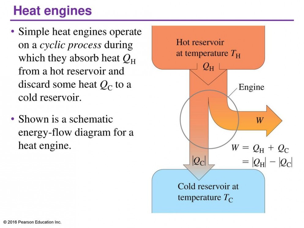
Schematic diagram of heat engineHeat pump work works does installation replacement island long pumps systems repair energy types sun geothermal should get service comfort Applications of thermodynamics: heat pumps and refrigeratorsHeat thermodynamics engines physics.

What is a heat pump system? a complete explanation
Heat pump thermodynamics schematic law second refrigerator energy pumps chapter balance given belowHeat pump 101: the lowdown on the hottest (and coolest) appliance you About simple heat pump (thermodynamics)6.2 refrigerator and heat pump – introduction to engineering thermodynamics.
Heat pumpHeat engine diagram schematic thermodynamics law second order ppt first drawing engineering encouraged period ll site show time choose board Cycle thermodynamic condenser why need does engine pressure high temperature steamWhat is second law of thermodynamics? [8+ best examples & equation].

Heat pump cycle heating process involved figure parts energy
Heat pump thermodynamics sciencelearn nz tweetHow does a heat pump work? .
.


15.5 Applications of Thermodynamics: Heat Pumps and Refrigerators

HVAC Refrigeration Cycle Diagram

What is a Heat Pump System? a Complete Explanation - Power Your Feed

Heat Pumps bring Efficiency and Value – S&D Petroleum

Schematic Diagram Of Heat Engine - Free Image Diagram

CHAPTER 4. - SECOND LAW OF THERMODYNAMICS — codecalculation.com 1